Release 8.0.4
A53264-02
Library |
Product |
Contents |
Index |
| Oracle8 Spatial Cartridge User's Guide and Reference Release 8.0.4 A53264-02 |
|
![]()
![]()
Oracle Spatial Cartridge is an integrated set of functions and procedures that enables spatial data to be stored, accessed, and analyzed quickly and efficiently in an Oracle8 database.
Spatial data represents the essential location characteristics of real or conceptual objects as those objects relate to the real or conceptual space in which they exist.
Spatial Cartridge is designed to make the storage, retrieval, and manipulation of spatial data easier and more natural to users such as a Geographic Information System (GIS). Once this data is stored in an Oracle8 relational database, it can be easily and meaningfully manipulated and retrieved as it relates to all the other data stored in the database.
A common example of spatial data can be seen in a road map. A road map is a two-dimensional object that contains points, lines, and polygons that can represent cities, roads, and political boundaries such as states or provinces. A road map is a visualization of geographic information. The location of cities, roads, and political boundaries that exist on the surface of the Earth are projected onto a two-dimensional display or piece of paper, preserving the relative positions and relative distances of the rendered objects.
The data that indicates the Earth location (latitude and longitude, or height and depth) of these rendered objects is the spatial data. When the map is rendered, this spatial data is used to project the locations of the objects on a two-dimensional piece of paper. A GIS is often used to store, retrieve, and render this Earth-relative spatial data.
Other types of spatial data that can be stored using Spatial Cartridge besides GIS data include data from computer-aided design (CAD) and computer-aided manufacturing (CAM) systems. Instead of operating on objects on a geographic scale, CAD/CAM systems work on a smaller scale such as for an automobile engine or much smaller scale as for printed circuit boards.
The differences among these three systems are only in the scale of the data, not its complexity. They might all actually involve the same number of data points. On a geographic scale, the location of a bridge can vary by a few tenths of an inch without causing any noticeable problems to the road builders. Whereas, if the diameter of an engine's pistons are off by a few tenths of an inch, the engine will not run. A printed circuit board is likely to have many thousands of objects etched on its surface that are no bigger than the smallest detail shown on a roadbuilder's blueprints.
Spatial Cartridge supports three geometric primitive types and geometries composed of collections of these types. The three primitive types are as follows:
2-D points are elements composed of two ordinates, X and Y, often corresponding to longitude and latitude. Line strings are composed of one or more pairs of points that define line segments. Polygons are composed of connected line strings that form a closed ring and the interior of the polygon is implied. Figure 1-1 illustrates the supported geometric primitive types.

Self-crossing polygons are not supported although self-crossing line strings are. If a line string crosses itself it does not become a polygon. A self-crossing line string does not have any implied interior.
The Spatial Cartridge data model is a hierarchical structure consisting of elements, geometries, and layers, which correspond to representations of spatial data. Layers are composed of geometries (or geometric objects), which in turn are made up of elements.
For example, a point might represent a building location, a line string might be a road or flight path, and a polygon could be a state, city, zoning district, or city block.
An element is the basic building block of a geometric feature for Spatial Cartridge. The supported spatial element types are points, line strings, and polygons. For example, elements might model star constellations (point clusters), roads (line strings), and county boundaries (polygons). Each coordinate in an element is stored as an X,Y pair.
Point data1 consists of one coordinate. Line data consists of two coordinates representing a line segment of the element. Polygon data consists of coordinate pair values, one vertex pair for each line segment of the polygon. Coordinates are defined in either a clockwise or counter-clockwise order around the polygon.
If an element spans more than one row, an incremental sequence number (starting at zero) orders the rows.
A geometry is the representation of a user's spatial feature, modeled as an ordered set of primitive elements. Each geometric object is required to be uniquely identified by a numeric geometry identifier (GID), associating the object with its corresponding attribute set.
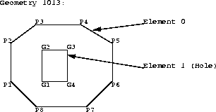
A complex geometric feature such as a polygon with holes would be stored as a sequence of polygon elements. In a multi-element polygonal geometry, all subelements are wholly contained within the outermost element, thus building a more complex geometry from simpler pieces.
For example, a geometry might describe the buildable land in a town. This could be represented as a polygon with holes where water or zoning prevents construction.
A layer is a heterogeneous collection of geometries having the same attribute set. For example, one layer in a GIS might include topographical features, while another describes population density, and a third describes the network of roads and bridges in the area (lines and points). Each layer's geometric objects and their associated spatial index are stored in the database in standard tables.
Spatial Cartridge uses four database tables to store and index spatial data. These four tables are collectively referred to as a layer. A template SQL script is provided to facilitate the creation of these tables. See Section A.1.1.2, "crlayer.sql Script" for details.
Table 1-1 through Table 1-4 describe the schema of a Spatial Cartridge layer.
Table 1-1 <layername>_SDOLAYER| SDO_ORDCNT | SDO_LEVEL | SDO_NUMTILES | SDO_COORDSYS |
|---|---|---|---|
| <number> | <number> | <number> | <varchar> |
| SDO_DIMNUM | SDO_LB | SDO_UB | SDO_TOLERANCE | SDO_DIMNAME |
|---|---|---|---|---|
| <number> | <number> | <number> | <number> | <varchar> |
| SDO_GID | SDO_ESEQ | SDO_ETYPE | SDO_SEQ | SDO_X1 | SDO_Y1 | ... | SDO_Xn | SDO_Yn |
|---|---|---|---|---|---|---|---|---|
| <number> | <number> | <number> | <number> | <number> | <number> | ... | <number> | <number> |
| SDO_GID | SDO_CODE | SDO_MAXCODE ** | SDO_GROUPCODE ** | SDO_META |
|---|---|---|---|---|
| <number> | <raw> | <raw> | <raw> | <raw> |
The SDO_MAXCODE and SDO_GROUPCODE columns are not required for the recommended indexing algorithm using fixed-size tiles.
The columns of each table are defined as follows:
Spatial Cartridge provides stored procedures that assume the existence of the layer schema as described in this section. While layer tables may contain additional columns, they are required to contain at least the columns described in this section with the same column names and data types.
Figure 1-2 illustrates how a geometry is stored in the database using Spatial Cartridge. The geometry to be stored is a complex polygon with a hole in it.
<layername>_SDOLAYER
| SDO_ORDCNT (number) |
|---|
|
4 |
<layername>_SDODIM
| SDO_DIMNUM (number) | SDO_LB (number) | SDO_UB (number) | SDO_TOLERANCE (number) | SDO_DIMNAME (varchar) |
|---|---|---|---|---|
|
1 |
0 |
100 |
.05 |
X axis |
|
2 |
0 |
100 |
.05 |
Y axis |
<layername>_SDOGEOM
In this example, the <layername>_SDOGEOM table is shown as an eight column table with four ordinates per row. In actual usage, Spatial Cartridge supports N-wide2 tables. The coordinates for the outer polygon in this example could have been loaded into a single row containing values for coordinates P1 to P8, and then repeating P1 to close the polygon. The coordinates would be stored in the SDO_X1 and SDO_Y1 through SDO_X9 and SDO_Y9 columns.
The data in the <layername>_SDOINDEX table is described in Section 1.5, "Indexing Methods".
A spatial index is considered a logical index as opposed to a physical index. The entries in the spatial index are dependent on the location of the geometric objects in the layer space, and are not dependent on the stored location of the data on the disk. This means that a table containing spatial data could be moved or split and the spatial index would not need to be rebuilt.
Spatial Cartridge release 8.03 introduced two distinct algorithms for building a spatial index: fixed-size tiling and variable-sized tiling. Based on testing and customer feedback, for release 8.0.4, Oracle recommends using only fixed-size tiling on production systems. Variable-sized tiling, while it has theoretical advantages in some situations, is included for experimentation purposes only.
In spatial indexing, the object space (the layer where all geometric objects are located,) is subjected to a process called tessellation, which defines exclusive and exhaustive cover tiles of every stored element. Spatial Cartridge can use either fixed-size or variable-sized tiles to cover a geometry.
The number of tiles used to cover an element is a user-tunable parameter. Using either smaller fixed-size tiles or more variable-sized tiles provides a better fit of the tiles to the element. The fewer the number of tiles or the larger the tiles, the coarser the fit.
The process of determining which tiles cover a given element is called tessellation. The tessellation process is a quad-tree decomposition, where the object space is broken down into four equal-sized covering tiles. Successive tessellations break those tiles down into four smaller tiles, and this process continues until the desired level has been achieved. The results of the tessellation process on an element are stored in the <layername>_SDOINDEX table. See Section 2.3, "Index Creation" for more information on tessellation.
Figure 1-3 illustrates geometry 1013 tessellated to a maximum of four cover tiles. The cover tiles are then shown stored in the <layername>_SDOINDEX table.
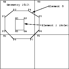
Only three of the four tiles generated by the first tessellation interact with the geometry. Only those tiles that interact with the geometry are stored in the
<layername>_SDOINDEX table, as shown in Table 1-5. In this example, three fixed-size tiles are used.
| SDO_GID <number> | SDO_CODE <raw> |
|---|---|
|
1013 |
T0 |
|
1013 |
T2 |
|
1013 |
T3 |
All elements in a geometry are tessellated. In a multi-element polygon like 1013, Element 1 is already covered by tile T2 from the tessellation of Element 0.
Fixed-size tile spatial indexing is the recommended indexing method. This method uses cover tiles of equal size to cover a geometry. Because all the tiles are the same size, the standard SQL equality operator (=) can be used to compare tiles during a join operation. This results in excellent performance characteristics.
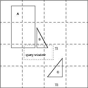
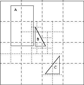
If you select a small fixed-size tile to cover small geometries and then try to use the same size tile to cover a very large geometry, a large number of tiles would be required, thereby increasing the size of the index table. However, if the fixed-size tile size chosen is large, so that fewer tiles are generated in the case of a large geometry, then the index selectivity suffers because the large tiles do not fit the small geometries very well. Figure 1-4 and Figure 1-5 illustrate the relationships between tile size, selectivity, and the number of cover tiles.
Using a small fixed-size tile as shown in Figure 1-4, selectivity is good, but a large number of tiles is needed to cover large geometries. A window query would easily identify geometries A and B, but would reject C.

Using a large fixed-size tile as shown in Figure 1-5, fewer tiles are needed to cover the geometries, but the selectivity is poor. A window query would likely pick up all three geometries. Any object that shares tile T1 or T2 would identify object C as a candidate, even though the objects may be far apart, such as objects B and C are in this figure.
Use the SDO_TUNE.ESTIMATE_TILING_LEVEL() function to determine an appropriate tiling level for your data set.
|
Note: Variable-sized tile spatial indexing is not recommended for production environments. It is included primarily for experimentation purposes. |
Variable-sized tile spatial indexing uses tiles of different sizes to approximate a geometry. The user specifies the number of tiles per object that should be used to approximate it and this governs the tiling process. As in the case of a linear quad tree, the cover tiles depend on the size and shape of each geometry being indexed and therefore good primary filter selectivity can be achieved. Figure 1-6 illustrates the approximation that variable-sized tiles can achieve.
In Figure 1-6, the variable-sized cover tiles conform closely to each geometry, resulting in good selectivity. The number of tiles needed to cover a geometry is controlled using the SDO_NUMTILES column in the <layername>_SDOLAYER table. See Section 2.3.3 for information on selecting appropriate values for variable-sized tiling.
Two geometries may interact if a tile of one object is equal to, inside of, or contains a tile of the other. Thus, the query predicate to compare tiles involves a test for either equality or containment. This is unlike fixed-size tiling, which only requires an equality check. Example 1-1 demonstrates this feature ("5" is an arbitrary window identifier).
SELECT r.sdo_gid
FROM roads_sdoindex r,
     window_sdoindex w
WHERE w.sdo_gid = 5
  AND (r.sdo_code BETWEEN w.sdo_code AND w.sdo_maxcode OR
       w.sdo_code BETWEEN r.sdo_code AND r.sdo_maxcode);
To reduce the number of times a complex predicate needs to be applied, variable-sized tile indexing uses a mechanism similar to spatial partitioning. To use this mechanism, select a tiling level, called the groupcode level, that results in tiles larger than any variable-sized tile generated for all the geometries in the layer or data set of interest. Each tile at the specified groupcode level can be considered a spatial partition. This reduces the size of the data set on which the complex predicate is evaluated. Example 1-2 illustrates this feature.
SELECT r.sdo_gid
FROM layer_sdoindex r,
     window_sdoindex w
WHERE w.sdo_gid = 5
  AND r.sdo_group_code = w.sdo_groupcode
  AND (r.sdo_code BETWEEN w.sdo_code AND w.sdo_maxcode OR
       w.sdo_code BETWEEN r.sdo_code AND r.sdo_maxcode);
In Figure 1-7, consider the domain partitioned into 16 subregions. If a join compares tiles from the two objects, under normal circumstances the join operation would process tiles from the entire domain, searching for tiles that interact. However, if you constrain the processing to common partitions, then only partitions 5 and 6 would need to be processed. This may result in substantial performance improvements.

Spatial Cartridge has an enhanced spatial indexing mechanism capable of handling very large datasets consisting of complex geometries. For applications handling point datasets that are several tens of gigabytes or larger, further performance gains can be achieved by using Oracle8 table partitioning features.
Table partitioning is only available with the Partitioning Option of Oracle8 Enterprise Edition. If the Partitioning Option is available to you, the preferred method is to use Oracle8 table partitioning in conjunction with Spatial Cartridge spatial indexing (see the Oracle8 Concepts guide for a description of Oracle8 Partitioning). A technical white paper titled, "Leveraging Oracle8 Partitioning and the Spatial Cartridge for Large Point Datasets," describing the use of partitioning and spatial indexing for point datasets may be obtained from the Oracle corporate web site at:
http://www.oracle.com/st/cartridges/spatial/collateral
A previous release of Spatial Data Option (from which Spatial Cartridge has evolved) utilized its own version of table partitioning instead of spatial indexing. Chapter 4 briefly describes the old partitioning scheme for those customers with legacy point datasets. Any references to point data partitioning in this manual (such as the "Partitioned Point Data Procedures" section in Chapter 5) refer to this legacy feature. While this feature is still available in Spatial Cartridge, the preferred approach is to use Oracle8 Partitioning Option and spatial indexing.
1
Point data can also be stored in a partitioned table. See Chapter 4, "Partitioning Point Data" for details.
2
A <layername>_SDOGEOM table can have up to 255 columns. The maximum number of data columns is 255, minus 4 for the other required spatial columns, and minus any other user-defined columns. For polygon and line strings, storing 16 to 20 ordinates per row is suggested for performance reasons, but not required.