Pinouts

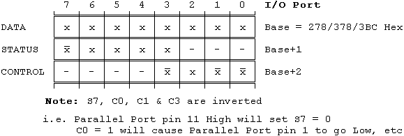
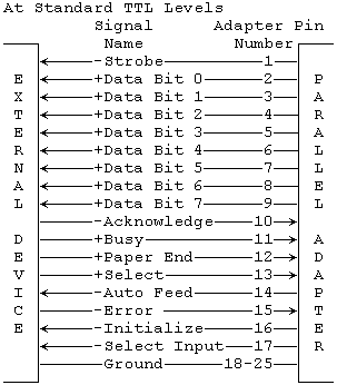
             Register  DB-25     I/O
Signal Name    Bit      Pin   Direction
===========  ========  =====  =========
-Strobe        ¬C0       1      Output
+Data Bit 0     D0       2      Output
+Data Bit 1     D1       3      Output
+Data Bit 2     D2       4      Output
+Data Bit 3     D3       5      Output
+Data Bit 4     D4       6      Output
+Data Bit 5     D5       7      Output
+Data Bit 6     D6       8      Output
+Data Bit 7     D7       9      Output
-Acknowledge    S6      10       Input
+Busy          ¬S7      11       Input
+Paper End      S5      12       Input
+Select In      S4      13       Input
-Auto Feed     ¬C1      14      Output
-Error          S3      15       Input
-Initialize     C2      16      Output
-Select        ¬C3      17      Output
 Ground          -     18-25       -
(Note again that the S7, C0, C1 & C3 signals are inverted)
IBM-PC Parallel Printer Port Female DB-25 Socket external Pin layout
 ______________________________________________________
/                                                      \
\  13  12  11  10   9   8   7   6   5   4   3   2   1  /
 \                                                    /
  \  25  24  23  22  21  20  19  18  17  16  15  14  /
   \________________________________________________/
So it's also the Pin layout on the solder side of the Male DB-25 Cable Connector that plugs into it